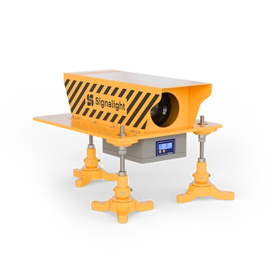
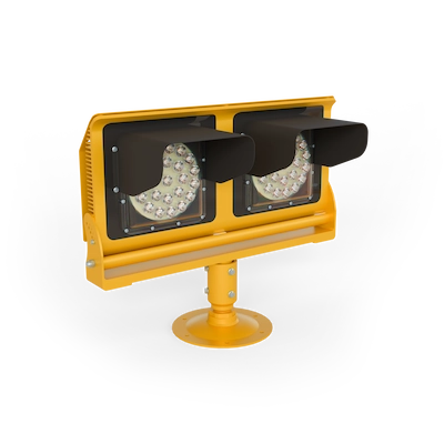
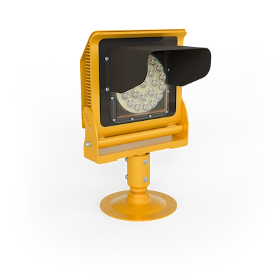
Precision Approach Path Indicator – APAPI
AL 088-30-WH-RE
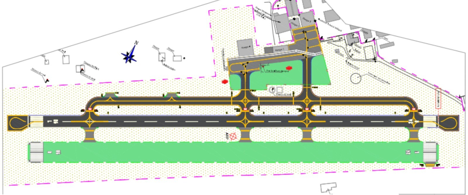
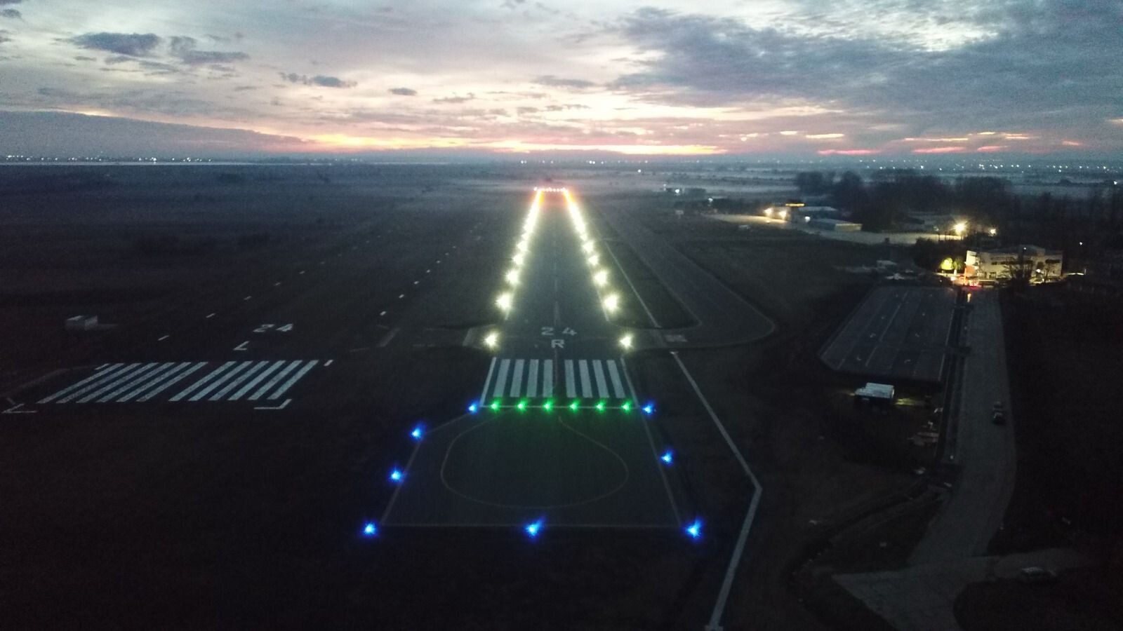
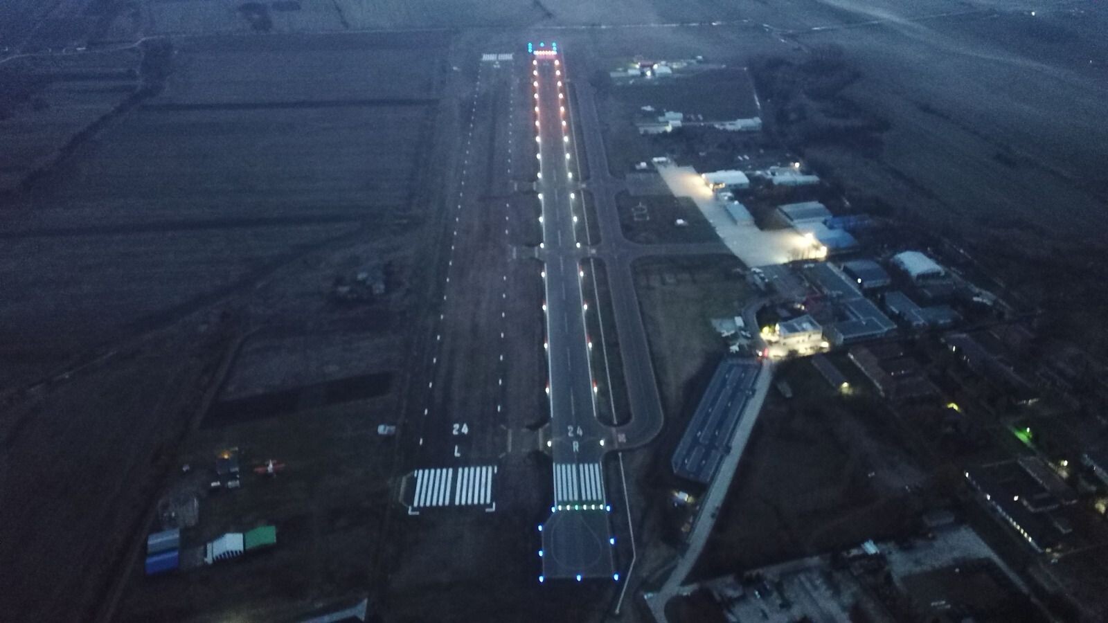
The Clinceni aerodrome is located south west of Bucharest. It has two parallel runways with a lenght of 1000m, oriented on directions 06 and 24, suited for gliders and light aircraft: a grass runway, used mainly for the glider, and a concrete runway. The low buildings and plain landform in the surrounding area of the aerodrome make it an ideal place for aeronautical activities, such as flight lessons, competitions and leisure flights.
For this project we used a complex VISTA system with 14 circuits: 8 circuits with brightness control, and 5 circuits powered from 230V, in which the devices dim automatically to 10% during night time. TAXI edge lights are powered into a serial conection with constant current. Therefore, we used the following 14 independent circuits:
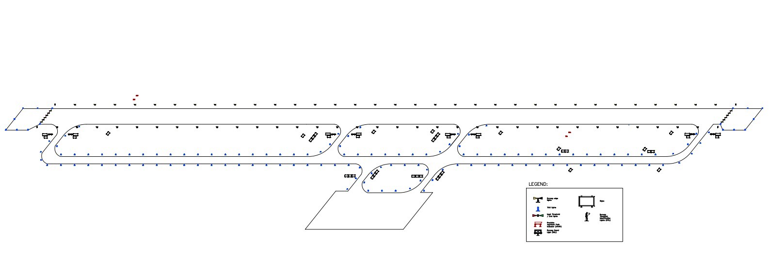
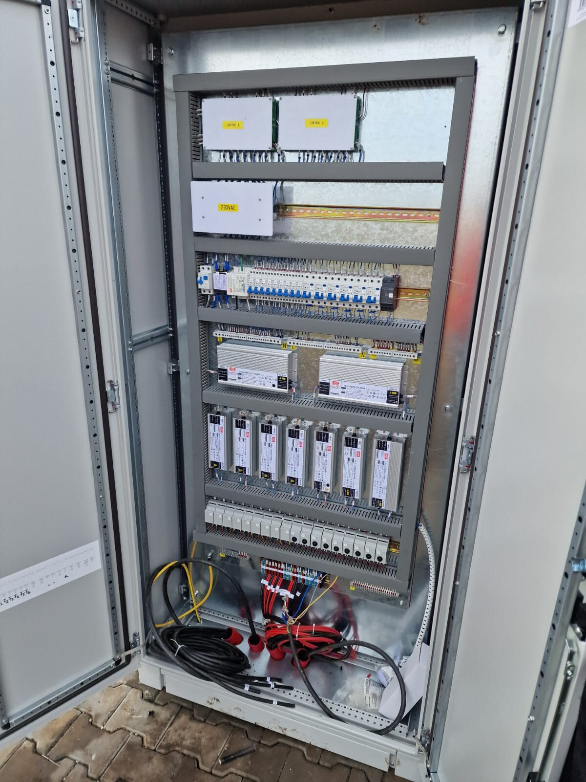
All the circuits are powered, controlled and monitored by the V4 controller. The control is made using the local console.
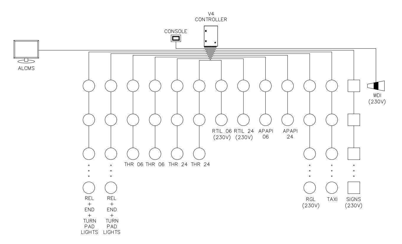
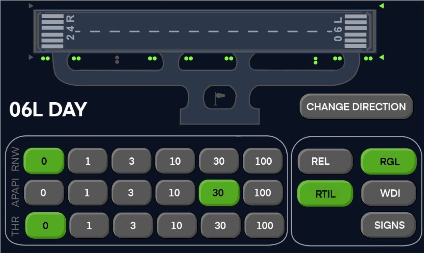
There is the possibility of controlling the airport lighting system using a console with LCD touch screen, located close to the V4 controller. There are predetermined scenarios, but the user can change the brightness step of any adjustable circuit:
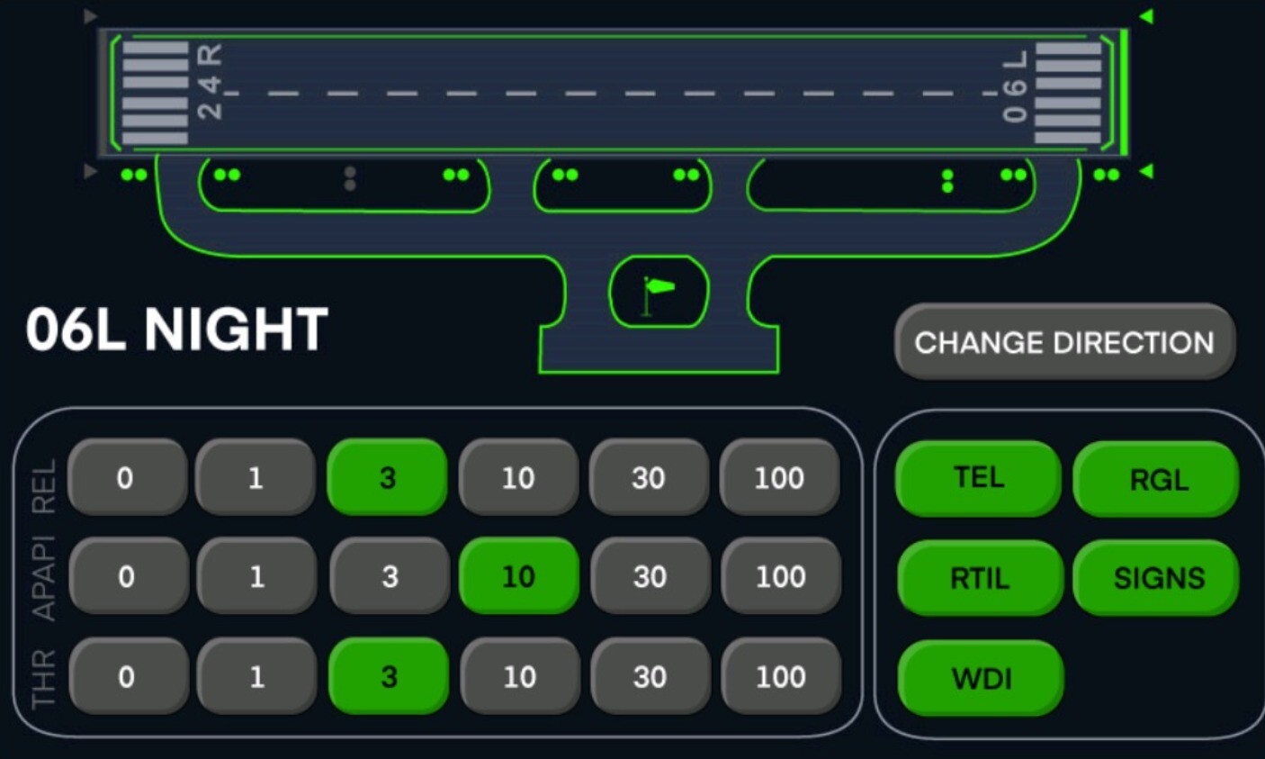
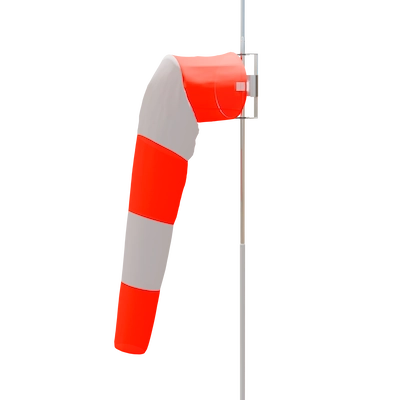
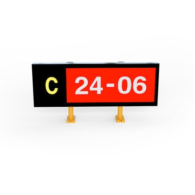
The runway lights and the threshold are powered at 3% brightness and the TAXI edge lights (TEL), runway guard lights (RGL), runway threshold identification lights (RTIL), signs and wind direction indicator (WDI) are switched on. Runway guard lights (RGL) and runway threshold identification lights (RTIL) will have 10% of the brightness because of the photocell sensor. Only the precision approach path indicator (APAPI) and runway threshold identification lights (RTIL) from direction 06 are powered, and the ones from direction 24 are turned off.
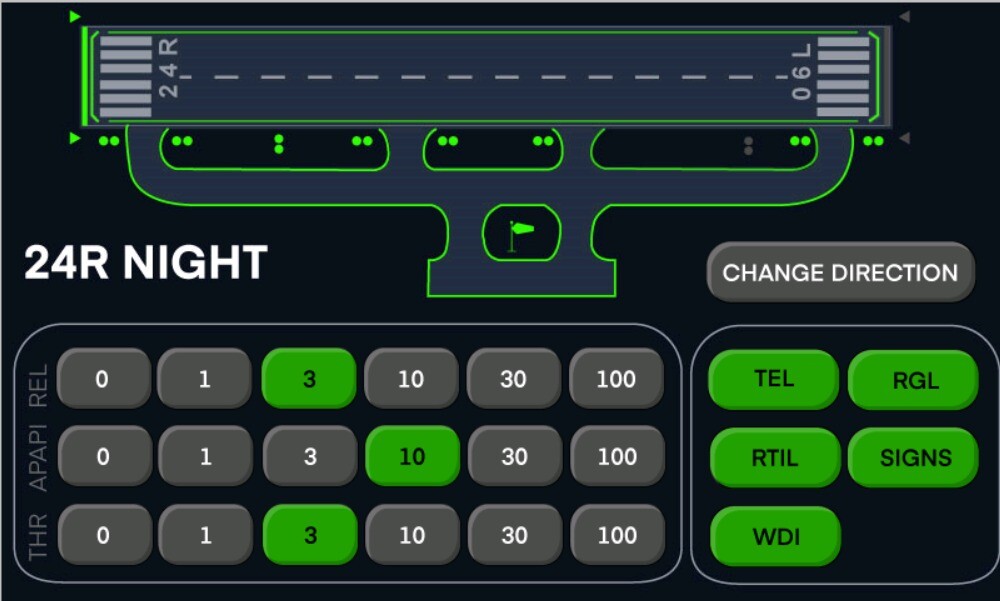
The runway lights and the threshold are powered at 3% brightness and the TAXI edge lights (TEL), runway guard lights (RGL), runway threshold identification lights (RTIL), signs and wind direction indicator (WDI) are switched on. Runway guard lights (RGL) and runway threshold identification lights (RTIL) will have 10% of the brightness because of the photocell sensor. Only the precision approach path indicator (APAPI) and runway threshold identification lights (RTIL) from direction 24 are powered, and the ones from direction 06 are turned off.
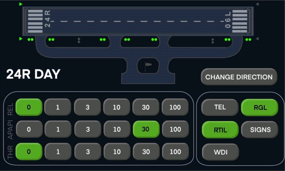
The runway lights and the threshold are not powered and the runway guard lights (RGL) and runway threshold identification lights (RTIL) are switched on. Runway guard lights (RGL) and runway threshold identification lights (RTIL) will have 30% of the brightness because of the photocell sensor. Only the precision approach path indicator (APAPI) and runway threshold identification lights (RTIL) from direction 24 are powered, and the ones from direction 06 are turned off.
The runway lights and the threshold are not powered and the runway guard lights (RGL) and runway threshold identification lights (RTIL) are switched on. Runway guard lights (RGL) and runway threshold identification lights (RTIL) will have 30% of the brightness because of the photocell sensor. Only the precision approach path indicator (APAPI) and runway threshold identification lights (RTIL) from direction 06 are powered, and the ones from direction 24 are turned off.
Airfield Lighting Control and Monitoring System (ALCMS) is a monitor with a 27 inches touch screen and computer intergrated, connected to the V4 controller, located in the control tower. The airport lighting system control is managed from an application containing the predetermined scenarios listed above. It includes pilot view, a user access function, an action log and an error log.
Every serial circuit is monitored for open loop failures. In case the serial circuit is interrupted, the power supply is cut off and an error is signaled.
The parallel circuits powered from 230V AC are monitored for possible earth leakage.

| Location | Clinceni, Romania |
| Application | Airport Lighting Projects |
| Date | December, 2023 |
AL 088-30-WH-RE
AL-026-48-XX (XX = RE or AM)
AL-080-24-WH
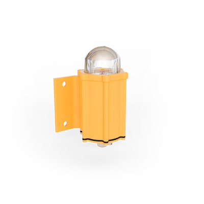
AL-OBS-05-XXX
AL-081-XX
AL 070-XXX-XX
For any question you want to ask, price quote, technical support or maybe just a quick piece of advice, don't hesitate to contact us.